|
Scale
Lumber, Building Kits and related Products for Garden Railroading. Our
Kits can make the Novice Modeler look like a Pro!
|
| Visit Our Store |
| SPJRR Howe Truss Bridge
& Expansion Kits |
(click on photo's for a larger image)
| |
Scale
Lumber, Building Kits and related Products for Garden Railroading. Our
Kits can make the Novice Modeler look like a Pro!
|
| Visit Our Store |
| SPJRR Howe Truss Bridge
& Expansion Kits |
(click on photo's for a larger image)
Glue Tips,
Not much glue needed for this kit but if you decide to use it for the base assembly use waterproof glue suitable to your climate. As with all glues excess is best cleaned up before it sets. If you will be doing a clear finish, we have found that small glue mistakes don't show if clear setting glue is used. Still it is best to clean up, especially areas where a hardened glob interferes with further construction. (Easier to remove a soft lump than a hard glob)
Cutting Tips,
The only cutting necessary is the length of the track stringers and if you want to trim the ends of the top and bottom beam assemblies at each end of the bridge. Always cut longest elements first and use the leftovers for the smaller items.
Overall dimensions (full size) are 21' wide x 50' long x 22' tall, which is 10 1/2" x 25" x 11" tall in scale size for the base bridge kit. Inside dimensions are 7" wide between the inside truss rods and 9 ½" from top of the track stringers to the bottom of the cross beams. The expansion kits available in 12" and 24" length and you can add one or multiple expansion kits to lengthen your bridge to fit your needs. Actual length is 25" so you can use ½" on each end over your bridge abutments and still have a 24" span underneath. Assembly of the base bridge for this tips page took less than 1 hour and included the time to take the photos!
If you are adding one of our expansion kits assemble the base (cross beams and stringers) from the expansion kit plan set. Look at the part orientation of the top and bottom 4x12 beams. The bridge side trusses assemble in 4 halves that attach overlapped at the center to form the bridge. If you are adding our 12" or 24" expansion kit you can assemble both kits at the same time starting with the side trusses. It isn't necessary to use glue on the side trusses and I don't recommend it. But if you do, use a slow setting exterior glue so you have time to work with the parts for alignment purposes when you get to joining the halves together to form a single side truss. One last note before we start, the diagonals part #5 and #6 are actually the same but it is easier to explain assembly in layers using different part numbers. The nuts require a 3/16" wrench or nut driver and if you over tighten and strip any threads there is a note later about this.
Rod Prep: The rods are shipped with a light coating of machine oil to control tarnish in storage. Wash them with mild soapy water (dish soap works well) and dry with a soft rag. If there are tooling marks towards the center of the long rods from the threading process clamp fixture you can lightly file or sand them if you desire. Once assembled they were hardly noticeable so we didn't bother on the prototype. The short rods don't matter as just the very ends show. Rods can be coated with clear polyurethane if you want them to remain brass color or you can leave them uncoated and after a few months they will get a natural brown patina that looks great. There are also coloring or tarnish agents you can get from craft stores to speed this process up.
Start with the longest (part # 3 for the top beam assembly and part # 4 for the bottom beam assembly)
We put a washer and nut on one end of each cross rod.
Cross rods nut and washer side under the first beam part sticking up so we can add the next layer. 3 cross rods in the top and bottom beam for now.
Note end angle orientation of the first row of #5 diagonals.
Next layer of beam parts #2 for the top and #3 for the bottom then next row of #6 diagonals with spacer blocks part #7 (first 2 on the left side bottom beam).
Last beam parts # 1 for the top beam and #2 for the bottom beam. Don't forget each nut should get a washer underneath it. Just finger tight for now and try to keep equal amounts of thread sticking out on each side. The holes are all drilled 1/64" of an inch larger than the rod size to give a little fudge factor for small adjustments.
Continue until you get all 4 halves done. If you are adding an expansion kit then drop down to the section below on expansion kits. Then return back here to continue final assembly.
Join the side halves (you just take one and flip it over since they are all mirror images of each other). Start tightening the cross rods at the center and force the joints of the beam ends as tight together as possible
Final Assembly and Base Construction
End view, note rod has fairly equal thread sticking out each side.
Both side truss panels. It is important that they are sitting flat on a flat surface. Since there is a certain amount of flex in cedar and the holes are drilled 1/64" oversize to make assembly easier if you do final tightening on an uneven surface it could end up other than straight.
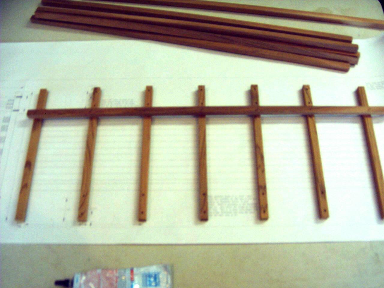
Please read this whole paragraph before starting this stage. If you are adding an expansion kit use the base drawing that came with that kit so you come up with the correct overall length. If you are adding multiple expansion kits understand you will have to adjust this base drawing. It isn't hard, just remember the cross beams are all on 4" centers except for the end ones. Note this dimension is on the drawing. Start with laying the 12x12 cross pieces on the plan. Note the end ones should not be drilled. All others have 2 holes drilled on each end and the holes should be pointing up so the side rods can go through them and up the sides of the side truss assemblies. We left the 12x12 stringer material hang over each end and cut it after all were tacked in place. We started with one side and worked our way across using a drop of slow set Bond 527 glue at junction and tacking with a pneumatic nailer using 3/4" long 18 gauge brads. You don't have to do each junction as we did but I like to tie things together tight. If you don't have an air nailer small brads can be hand nailed in place as well. After we were done we realized it would also be possible to place the stringers on the plan first and add the cross beams on top which leaves the nails showing from the bottom after the bridge is finished. If you don't want the nail holes to show you might want to consider this.
The finished base with the ends of the stringers trimmed flush with the outside ends of the end cross beams.
Base and both side truss assemblies ready to assemble. If you are doing hand laid track then your ties can be attached to the top of the stringers and it might be easier to assemble the bottom, attach your ties then the rail and assemble the bridge over the top.
I held the base upside down and placed the side rods with a nut and washer on one end through the cross beam holes.
The base turned over and side trusses placed between the rods. Add the top drilled cross beams.
Continue and also add washers and nuts. Looking down the length of the bridge keep the side truss assemblies centered side to side between the vertical rods. Bottom of side truss should be centered between rods and lengthwise on the base. The top cross beams should be centered over the cross rods. An easy way to do this is to just line up the side rods with the cross rods at the bottom side of the top cross beams. Before final tightening look at the square ends of the side truss beams and decide if you want to trim them. We chose not to. Final tighten and call it a bridge. See completed photos below at end of page.
!!!!!
If you over tighten a rod and strip the threads which is easy to do on this small thread, don't worry. A simple fix is to clean the end of the rod with soap and water to remove any oil left from the threading process. Then put the nut in place leaving thread showing similar to others next to it and put a drop of super glue on it. Put it back in place and add the washer and nut to the other end.
We are showing the 12" expansion kit the procedure is same for the 24". The important thing to remember is to understand the top views of the beam assembly from the drawing and then proceed.
Half of the base bridge kit side truss.
Truss half with the first layer of beam parts. Part #8 for the 12" expansion and part #9 for the 24" expansion kit.
Important thing to know at this point. All three kits are designed on the cross rod holes being on 4" centers. The base bridge ends up being 25" long because of the end material beyond the center of the end hole for the cross rods. The expansion kits add 12" or 24 inches to this. Another twist to this is you could cut the expansion kit beams shorter in 4" increments if desired just cut it at the center of the cross rod hole. I don't recommend this for the 12" expansion kit but it will work great for the 24" kit. To shorten the beams on the 12" kit will cause you to lose the 3 joint lap that in reality gives you the most beam strength possible with an expandable kit like this. If you do decide to cut down a 12" expansion kit I strongly recommend you end glue the beam parts. If you are adding multiple expansion kits understand you will have to adjust this base drawing. It isn't hard, just remember the cross beams are all on 4" centers except for the end ones. Note this dimension is on the drawing.
Notice second side orientation to the first layer of beams.
Diagonals lower level added. We found it easier to add the layers and later insert cross rods from the top.
Next layer of beams part #8 for the 12" expansion and part #9 for the 24" expansion kit.
Next layer of diagonals.
Final layer of beams.
This is the tricky part. We drilled all the holes 1/64" over size to make this easier. Line up the holes and push a cross rod through. Continue and add nuts and washers on this side.
I have the bottom hanging just barely over the edge of the table. The topside nuts and washers are on and I am adding the nuts and washers to the bottom. Be careful not to slide the assembly to far over the edge until you get at least bottom side nut on in the center of the bottom most beam of the pile or it might fall off.
Flipped the assembly over and continued with the top.
Finished side truss with 12" expansion section added standing in front of original base bridge kit. I had removed one side for doing the expansion. Now continue with the other side. Make the base for the new expanded bridge based on the base drawing that came with the expansion kit. Since the bases' stringer material comes in 24"-25" length there will be joints in the stringers of the base assembly. We recommend staggering them as shown on the drawing for added strength so the joints don't appear on the same lower cross beam. Return to final assembly and continue as you would for the base bridge up above on this tips page..
With a piece of Aristo track and a Hartland 440. Since our kit includes the stringer material as well you are ready for sectional track or attach your ties for hand laid track if that is your thing.
A great kit just for displaying your favorite loco. Side and cross rods add nice detail.
All lumber in this kit is our highest grade of lumber and is finish sanded so you are ready to use it as a display bridge as well as on your layout. It may need some light sanding for end burs left from cutting to length.
Ready to finish with stain, clear or just let it weather to a natural cedar gray.
A couple shots of all three kits assembled hanging from the dust collector piping in the shop. The 25" base bridge with the 12" & 24" expansion kits added in the middle for a total length of 61"
Total construction in this configuration was about 2 hours.
Good Luck and Happy Railroading!
Thanks,
Mark & Sue Smith
Smith Pond Junctions Railroad Products
Team@spjrr.com
Little Lumber is Our Business
All Rights Reserved